 FORUM
FORUM Sales / Scratch & Dent
The Novak Guide to
Clutches, Linkages & Bellhousings for Jeep® Conversions
This article contains the culmination of decades of experience setting up clutch systems for Jeep conversion applications. We will first identify the components involved, and then introduce the science of setting up a proper clutch release system.
Flywheel
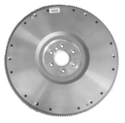 The flywheel provides a friction surface for the clutch disc, a torque buffering mass, a mounting
surface for the pressure plate, a mounting for the starter driven gear, and on some engines the flywheel is a
factor in engine balance.
The flywheel provides a friction surface for the clutch disc, a torque buffering mass, a mounting
surface for the pressure plate, a mounting for the starter driven gear, and on some engines the flywheel is a
factor in engine balance.
The condition of the friction surface of the flywheel is important for proper clutch function. The surface should be smooth and free of burned spots and surface cracks. Used flywheels can be resurfaced. This should be done by grinding rather than lathe turning as less material is removed. The amount of material removed from the face can affect which clutch release bearing should be used. A flywheel should always be checked for runout on the engine it will be used on. Face runout should not exceed .005" of an inch.
Pressure Plate▼
 This is the other half of the driving friction surface. It mounts on the flywheel. It consists of
four main parts and is more correctly called a clutch cover assembly. These parts are the pressure plate itself,
the springs (or spring, if a diaphragm type), the clutch cover, and the release arms. There are two basic
designs of clutches usually referred to by the spring type.
This is the other half of the driving friction surface. It mounts on the flywheel. It consists of
four main parts and is more correctly called a clutch cover assembly. These parts are the pressure plate itself,
the springs (or spring, if a diaphragm type), the clutch cover, and the release arms. There are two basic
designs of clutches usually referred to by the spring type.
These are the Rockford™ (diaphragm spring type) and the Borg and Beck™ (coil spring type). The coil spring type is also called a three-finger type, referring to the three release arms this style requires to compress the coil springs.
Our research shows that a typical GM clutch pressure plate, whether three-finger style or diaphram, 10-1/2" or 11" generally requires 0.550" of travel at the fingers to release the clutch disc.
Some common Jeep pressure plates require about 0 390" of travel to release.
The "softest" clutch is the diaphragm type. It also requires the least amount of travel to release. The diaphragm type clutch works good in lightweight, low geared vehicles. It is not the best clutch for high RPM use as the diaphragm spring will stay "flat" or released from the centrifugal force generated by the RPM. A variation of the diaphragm type was used for a while by GM, that to some extent helped this problem. This was called the Hi-Cone diaphragm type and was designed so the spring - instead of being flat when released - still had a slight bevel. These Hi-Cone units were not bad but still won't hold like the Borg and Beck coil spring type. Aftermarket units like the Centerforce®, use centrifugal weights to counteract this high-rpm flattening and subsequent loosening. It should be noted that this is not typically a concern of the Jeep enthusiast as high RPM horsepower is not as much an interest as low-RPM torque. It should be pointed out that the spring itself is the "release arms" of a diaphragm type clutch. Note that when interchanging from one type to the other, you will require a different throwout bearing. The three-finger style requires a longer throwout vs. the diaphram type, which uses a shorter throwout bearing. More on this later...
 The fourth part of the pressure plate assembly is the cover. The pressure plate, spring (or
springs) and release arms are attached to the cover in such a manner that, when the release bearing pushes on
the three arms or the diaphragm spring, it causes a leveraged action to take place. This counteracts the spring
pressure and lifts the pressure plate off the clutch disc, releasing the clutch.
The fourth part of the pressure plate assembly is the cover. The pressure plate, spring (or
springs) and release arms are attached to the cover in such a manner that, when the release bearing pushes on
the three arms or the diaphragm spring, it causes a leveraged action to take place. This counteracts the spring
pressure and lifts the pressure plate off the clutch disc, releasing the clutch.
As stated above, the diaphragm type clutch takes slightly less travel to release and requires about .030 total air gap when released. The coil spring type requires about .040 to .050 total air gap when released. Air gap is the clearance between the clutch disc, flywheel, and pressure plate with the clutch released. A total air gap of .050 will measure .025 between each side of the disc.
Clutch Disc
 This is the "driven" part of the clutch. It has a friction material riveted to each
side of a wavy spring (called a marcel). This is attached to a splined hub that the transmission input gear
protrudes into.
This is the "driven" part of the clutch. It has a friction material riveted to each
side of a wavy spring (called a marcel). This is attached to a splined hub that the transmission input gear
protrudes into.
There are basically two common types of friction material used for clutch lining. These are organic and metallic. The organic is best for all around use. The metallic is preferred by some for severe duty applications but requires high spring pressures and is hard on the flywheel and pressure plate friction surfaces. Avoid solid hub clutches and clutches without marcel as they will always chatter when used in vehicles with a rear differential mounted on springs (as opposed to a transaxle design).
Pilot Bushing▼
 In most cases, this is a porous bronze, pre-lubed bushing rather than an actual
bearing, as it is often called. A few applications still use an actual bearing and others use a needle roller
type bearing, but by far, the most common type is bronze. you cannot use a roller bearing on a transmission
shaft originally designed for a bronze bushing due to different type of heat treatment on the shafts.
In most cases, this is a porous bronze, pre-lubed bushing rather than an actual
bearing, as it is often called. A few applications still use an actual bearing and others use a needle roller
type bearing, but by far, the most common type is bronze. you cannot use a roller bearing on a transmission
shaft originally designed for a bronze bushing due to different type of heat treatment on the shafts.
For a list of several versions of pilot bushings offered by Novak, jump here.
The pilot bushing is seldom thought of as a part of the clutch system but it is one of the most vital parts of the system. It pilots the end of the transmission input gear in the crankshaft. If it is worn or not running "true", it can cause serious clutch problems or transmission failure. Pilot bushing bore runout should always be checked with a dial indicator and should be within .002 total. The bronze bushing type should be a press fit in the crankshaft bore. It must be installed carefully. It should have between .002 and .003 clearance on the transmission shaft when installed. The pilot bushing is only functional when the clutch is disengaged but it is a factor in input gear alignment at ALL times.
Most people have no idea what an important part the pilot bushing plays in the life of the transmission and clutch. The job of the pilot bushing is to support the end of the transmission input (main drive) gear in the crankshaft and it only acts as a bushing when the clutch is depressed. This pilot bushing should be a light drive fit into the crank bore. Care should be taken when installing any pilot bushing as they are soft and easily damaged by crude installation techniques. A damaged pilot bushing can bind on the input gear giving symptoms of clutch drag. Transmission damage and early failure can be caused by a pilot bushing or crankshaft bore that "runs out" in relation to the transmission locating bore in the bellhousing. It is advisable to check the bore of the crank with a dial indicator before installing the pilot bushing (see below). If the bore runs out more than .003 total, the crank should be set up in a lathe and the bore trued up OR a special pilot bushing should be made that runs out the same amount as the crank bore. The run out in the bore of a pilot bushing is put 180 degrees off from the crank bore run out and the pilot bushing installed. If properly done, this can put the bore of the pilot bushing well within the .003 required. We have used this method to save engine disassembly many times. A disadvantage of this method shows up at pilot bushing replacement time as a special pilot bushing will have to be reproduced.

Clutch alignment is critical to installation. Otherwise, expect the transmission to not line up with the pilot bushing.
It is always a good idea to use an input gear (of the proper diameter) or clutch aligning tool when installing the clutch on any engine. With the clutch disc aligned on the pilot bushing it becomes a simple matter when installing the transmission to engage the splines and bolt up the transmission . If this simple procedure is not done, the transmission shaft won't line up and the temptation will be great to "pull it up with the bolts" which damages the front transmission bearing, pilot bushing, and more than likely will break an ear off the transmission or adapter. The transmission should slip in freely to mate up with the face of the bellhousing.
Clutch Release Bearing▼
As its name implies, this is the bearing that releases the clutch. It is often referred to as a "throw-out"
bearing. They come on a number of different style carriers. The carriers, in some cases, vary considerably with
the particular engine. In the GM line, for example, the bearings are all the same but there are several
different carriers that vary about 1/2" between the shortest and longest. Which to use usually depends on the
style of pressure plate being used, but substituting one length for another can often be used to the installer's great advantage. AMC, Ford & Mopar
and others are far less generous with the variety of lengths available. This length issue is very critical and
this will be covered in more detail later in this article.
another can often be used to the installer's great advantage. AMC, Ford & Mopar
and others are far less generous with the variety of lengths available. This length issue is very critical and
this will be covered in more detail later in this article.
Because the release bearing only works when the clutch is being released it usually lasts quite a long time. However, improper linkage adjustment or riding the clutch with your foot when driving can wear the bearing prematurely. Normally there should be a 1/16" clearance between the face of the bearing and the three release fingers or diaphragm spring of the pressure plate when the clutch is engaged. This fact is important and will be discussed further when we get to the part about setting up the clutch linkage.
Clutch Release Fork▼
 This is the arm or lever that the linkage operates that moves the release bearing. There are
several different styles of release arm. The most common in automotive use is the fork type that pivots on a
rocker. This type requires a rearward force to move the release bearing forward. Note now that the following is
key to your understanding of the clutch system: The ratio of the arm is the difference in length between the
pivot point and the release bearing centerline divided by the length from the pivot point to where the linkage
attaches. The ratio of the fork is important and will be used in the linkage setup section later in this
article.
This is the arm or lever that the linkage operates that moves the release bearing. There are
several different styles of release arm. The most common in automotive use is the fork type that pivots on a
rocker. This type requires a rearward force to move the release bearing forward. Note now that the following is
key to your understanding of the clutch system: The ratio of the arm is the difference in length between the
pivot point and the release bearing centerline divided by the length from the pivot point to where the linkage
attaches. The ratio of the fork is important and will be used in the linkage setup section later in this
article.
GM, Ford, and AMC all use a pivot type release arm as their most common type. Some late GM, Pinto, Jeep and a few others use a non-rocker arm. This style pivots on the passenger side of center and is direct acting. That is, it takes a forward movement of the linkage to move the release bearing forward. This is not as suitable as the rocker system as it usually complicates the linkage requirements.
Regarding GM clutch forks, there are two basic types of manufacture used for the pivot type forks. These are stamped steel and forged steel. The stamped steel type uses a flat steel retainer spring that is riveted to the fork. These forks must be used with mushroom-head type pivots. The forged steel forks must use the ball-head type pivot. (This is different than the ball-on-pedestal AMC type.) These forged forks are retained on the pivot by a spring-wire retainer that fits in a groove machined in the ball pocket in the fork.
Release Arm Pivot▼
 As its name implies, this is the support that the
release arm pivots on. There are basically two types. One pivots on a ball-ended stud that screws into the
bellhousing. The other type is an actual bearing ball that sits in a pedestal type socket that is part of the
bellhousing. GM, Ford, and early AMC use the screw-in type. Late AMC featured the ball type.
As its name implies, this is the support that the
release arm pivots on. There are basically two types. One pivots on a ball-ended stud that screws into the
bellhousing. The other type is an actual bearing ball that sits in a pedestal type socket that is part of the
bellhousing. GM, Ford, and early AMC use the screw-in type. Late AMC featured the ball type.
There are factory GM style pivots, and aftermarket adjustable length pivots (shown) with an adjustment range of 1-3/8 to 1-1/2 inches available for GM engines that can sometimes be used to compensate for small variations in flywheel, clutch disc, and release bearing thickness. More about this in the troubleshooting section.
Both ball and mushroom-head GM pivots are available in 1-3/8 and 1-1/2" length (overall length when not [this is important] installed in the bellhousing). It is very important to use the correct style of pivot in relation to the type of arm being used.

On the left is the 1956-1981 short pivot as found in Firebirds, Vettes, Buicks and many others. It is found under part numbers, CLU-31, 3729000 and 28799. These were adequately long for factory clutches where GM had the right length release bearing available. But since not all these release bearing lengths are available now, this pivot is often too short for many factory and conversion type scenarios.
In the center is the longer GM pivot #15592268. This gives greater reach and a taller fulcrum in the GM bellhousing, but is not adjustable.
On the right is the Mr. Gasket #3855G (insert hyperlink here) pivot, which is just a bit longer than the long GM version, but has the benefit of shorter adjustability.
If you have an adjustable pivot, what's the adjustment priority: length of release bearing or length of pivot stud? The answer is: get your release bearing dialed in first, so it is just barely hovering off of the clutch pressure plate fingers at rest. Then, if you need to fine tune, use the adjustable pivot. Following this paradigm will solve most of the clutch release issues that installers commonly have. Do not use a long pivot to compensate for a overly short release bearing! your geometries won't be right and you risk popping the release bearing off the retainer tube and locking your clutch into a semi-released state.
Transmission Front Bearing Retainer
 This great device has three critical functions. This
first is as its name implies. The second is to provide a register on which the bellhousing must center to the
transmission. This is feature is sometimes overlooked with expensive consequences. Thirdly, its tubular snout is
the surface on which the throwout bearing rides on its way in to depress the springs of the pressure plate.
Conversions often require special and modified retainers to acheive compatibility.
This great device has three critical functions. This
first is as its name implies. The second is to provide a register on which the bellhousing must center to the
transmission. This is feature is sometimes overlooked with expensive consequences. Thirdly, its tubular snout is
the surface on which the throwout bearing rides on its way in to depress the springs of the pressure plate.
Conversions often require special and modified retainers to acheive compatibility.
Bellhousing
 This provides a mounting place for the transmission, as well as a means of aligning the
transmission to the engine. In some applications it also has a structural mounting function.
This provides a mounting place for the transmission, as well as a means of aligning the
transmission to the engine. In some applications it also has a structural mounting function.
The alignment function is extremely important. Unfortunately, this is the most often overlooked and least understood part about the bellhousing.
Most people who have worked on these parts realize there are aligning pins in the engine block that register with holes in the bellhousing. What they do not realize is, there can be a variation in the location of these holes and this variation can affect clutch and transmission life. How to check bellhousing alignment will be covered in its own section further on in this article.
Clutch Linkage▼
This consists of everything between your foot and the clutch release arm. The linkags is the method of transferring the force of your left foot into the bellhousing and pressure plate release. The linkage can be mechanical, cable type or hydraulic. Note here that problems tend to show up because there are usually several choices of release arms and bearings for any particular family of engines. Choosing the wrong parts can get the linkage out of relationship and cause problems that can only be solved by removing the parts and starting over with other parts. The linkage cannot be made to compensate incorrect choice of release bearing or fork.
Cable Style Linkage
 Cable linkages may seem appealing because it is easy to understand and simple to hook up. The
transportation industry has tried cables with great success in motorcycles, good success in cars, but they had
an unsustainable record in trucks, ranging from light to medium duty.
Cable linkages may seem appealing because it is easy to understand and simple to hook up. The
transportation industry has tried cables with great success in motorcycles, good success in cars, but they had
an unsustainable record in trucks, ranging from light to medium duty.
Some CJ & Commando Jeeps from 1972-1974 used a cable release, with subpar results as evidenced by the duration of their implementation.
A cable type clutch should probably be the last choice of the three types of linkages.
Mechanical Style Linkage
Next is the mechanical linkage which is, with a few exceptions, the type found on the majority of Jeeps® built prior to 1987.
There are several basic styles of Jeep mechanical linkage but all are used in nearly their original configuration when doing an engine conversion. They usually consist of a pushrod at the pedal, a bellcrank and an additional pushrod actuating the fork. Earlier systems use pullrods, bellcranks and cables in lieu of pushrods, effectively reversing the way the systems works.
The mechanical linkage is largely a successful method of clutch release. One drawback obvious to many off-roaders is the tendency of some of these to bind during frame and powertrain flex and differentiation.
Hydraulic Style Linkage
Hydraulic clutch linkage systems have moved into dominance in the past two decades, and generally with good reason.
The most common rendition of this linkage consists of the pedal pushrod against a master piston / cylinder, a high-pressure tube or line and a slave piston / cylinder whose pushrod pushes the clutch release arm.

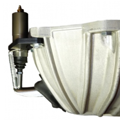
A less common style of hydraulic release is the internal hydraulic release bearing. This design combines the piston and bearing into one unit, eliminating the pivot, fork (or release arm) and separate throwout bearing.

A Jeep internal hydraulic throwout bearing, common in YJ Wranglers and XJ Cherokees between 1987-1994. They are innovative in design but have gained notoriety for leak failures. Hardened o-rings are usually the culprit, and this occurs as much from non-use (drying out) as overuse (abrasion wear).
To add serious insult to significant injury is to have the failure prone Peugeot BA10/5 transmission (1987-1988) with a bad internal release bearing.
A word is in order at this point about hydraulic clutches and the misconceptions that surround them. Many individuals believe that it is the interaction of the hydraulic master and slave cylinders through which the force against the clutch pressure plate is multiplied. In fact, the actual multiplication of force occurs in two different areas of the clutch system. First it is in the leverage of the clutch pedal assembly. The master cylinder actuator being closer to the fulcrum of the pedal arm, distance is reduced and force is increased, through that great principle of physics with which all mechanically minded individuals are aware. Secondly, additional force is created through the leverage of the clutch release arm. In basic principle, this is the way clutches have been virtually since the inception of the automobile.
The hydraulic system, therefore, is simply a method of transferring that leverage - or better said, of transmitting force through the incompressable hydraulic fluid. This is very similar in principle as a good old mechanical linkage via pushrods, bellcranks or cables. Essentially no multiplication of force occurs within the hydraulic circuit itself as is common with other hydraulic systems like jacks, rams and presses.

This is an aftermarket internal hydraulic throwout bearing. The drawback is the expense, at over $300
This leads to the next useful principle: Nearly every clutch master cylinder is matched for size to its connected slave cylinder for a largely 1-to-1 relationship. So, a 3/4" bore master cylinder should connect to a 3/4" slave cylinder. A 1" master should have a 1" slave cylinder. A master cylinder that is larger might yield a rather spectacularly blown out slave cylinder and a master cylinder that is smaller will yield a rather disappointing lack of travel for your left foot's efforts. There are occasions where this ratio can vary slightly from this, but rarely more than 15%.
Once the installer understands this, the rest will come together more easily and in accordance with the principles outlined for conventional mechanical clutch systems.
Hydraulic systems can be simple, but mostly when there are existing provisions for mounting the master and/or slave cylinders. Thin firewalls and bellhousings without proper structural provisions for slave cylinders are the chief entanglements that hamper retrofit.
Shown is Novak's hydraulic slave cylinder retrofit system for Chevy, Buick and Ford bellhousings. This makes excellent use of CJ, YJ & TJ Wrangler master cylinders as well as many others. Click here for more information...
Sequence of Linkage Setup
Let's assume we are using a Chevrolet engine, Rockford clutch (diaphragm type), and the back of the block is "bare" but the crankshaft is in the block.
Install the pilot bushing to be used for the particular engine-transmission combination in the crankshaft. Then, with a suitable dial indicator, check the bore of the pilot bushing. Runout should not exceed .002 (two thousandths) of an inch.
Temporarily install the bellhousing to be used on the block it will be used with. (This is important as the results of this test can vary with a different block or bellhousing.) Test the bellhousing for "runout" on both its bore and face as described in the trouble-shooting section. Bore runout must be within .007" and face runout to within .004". If you don't, can't, or won't check bellhousing alignment, do not be surprised if you have problems. These will not show up right away. It may be several thousand miles before a clutch hub, pilot bushing, or transmission fails.
Temporarily bolt the transmission to the bellhousing. Look through the release fork opening to determine that the pilot area is at least 3/8" engaged into the pilot bushing bore. If it is not, the pilot bushing is incorrect and a longer bushing must be installed, or in some cases, the bushing can be installed at less than full depth.
Remove the transmission and bellhousing. Install the flywheel on the engine. Most engines use grade 8 (high-strength) bolts with a special low profile head to clear the disc hub. Do not substitute regular bolts for these special bolts.
Check the face of the flywheel for runout with a dial indicator. Runout should not exceed .005". If it does, the flywheel should be resurfaced. If runout exists after resurfacing, the fault is either in the resurfacing job or there are burrs, dirt, or dings on the crankshaft or flywheel hub. Remember there is end play in the crankshaft bearings and this must be held in one direction when checking flywheel runout (or bellhousing face runout).
Install the clutch disc and pressure plate on the flywheel. Use a clutch aligning tool or the transmission itself. This is important as it will simplify transmission installation and prevent assembly damage. Tighten the mounting bolts 1/4 turn at a time so as not to distort the clutch cover.
Choosing a Release Arm
Stay alert on this step. Things get kind of involved but it is very important. If you're retaining your mechanical linkage (in lieu of hydraulic) the release arm must be the same ratio as the arm that was originally in the Jeep for the linkage to work. Notice we said ratio, not length. Assume the release arm is the typical rocker type with its pivot between the release bearing and the linkage attach point and figure the ratio as follows.
Measure the Jeep arm from the pivot point to the center of the clutch release bearing. Also, measure the distance from the pivot point to where the linkage attaches. Divide the inner length into the outer length to obtain the ratio of the arm. (Example: A stock Jeep arm from a 1976 CJ5 measures 3.1" from the pivot in and 6.2" from the pivot out to where the linkage pushes. Divide the 3.1" into 6.2" and you find this arm has a 2-to-1 ratio. This means if you move the end of the arm 1", the release bearing would have to move 1/2" in the opposite direction.)
Now assume we need a Chevy arm to work with this same linkage. Chevy arms all measure 3" from the pivot in. We need a 2-to-1 ratio (as this is what the Jeep linkage and many GM pressure plates are designed for) on the Chevy arm so we require a Chevy arm 6" long from the pivot out. Unfortunately no such Chevy arm exists. The shortest non-hydraulic arm is 6.5" from the pivot out. Some are as much as 9" pivot out. The short arm is 2.17 to 1 and the long arm is 3 to 1. The long arm must be shortened 3" to be compatible with the linkage. What about the short arm? you could make it work on this particular vehicle by sacrificing some free play (at the release bearing) as well as air gap at the disc (full release condition). This particular short Chevy arm also has an end shape that is correct for the Jeep linkage we used as an example. This 6½" long Chevy arm is available from Novak as our #RAGM.
All of this changes when a vehicle with different style original linkage is being worked on.
The early style CJ's (pre-1971 with 4 cylinder) for example, had a very short release arm; the remaining leverage occurs additionally in the linkage system. However, if this arm is measured from the pivot in and divided into the pivot out length it will be found to have a ratio of 2.4" to 1. As previously stated, there is no factory GM release arm with the required outer length that has the proper type end. A longer arm can be shortened and the end modified to accept the Jeep linkage. However, Novak has these arms available as our #RAV6.
From all this, it should be observed that the release arm to be used with a conversion will sometimes have to be modified to get the proper ratio and this must be done at the start of the installation. Trying to use an arm that is too long will result in problems that cannot be corrected with changes in linkage.
Choosing the Right Release Bearing
This is the part where most people err in setting up their clutch systems. No fix, no bandage, no compensation and no adjustment will make up for the wrong choice of throwout / release bearing. The length of clutch release bearing has the most significant effect on the operation of a clutch of any other factor, and for decades, too many clutch projects have been plagued with set-up problems due to improper bearing lengths.
The very first assumption one must ditch is this: "My clutch kit came with a release bearing, therefore, it must be the correct one." In fact, we now recommend that installers buy the clutch bearing separate from the clutch kit, and that the purchase the bearing afterwards based on a mocked-up measurement.
The following procedure should help you to determine which of the different length clutch release bearings you will need to properly operate the clutch.
Install the flywheel, clutch disc, pressure plate and clutch housing on the engine. Be advised that there can be no oil or grease on your hands, the flywheel or pressure plate friction surfaces, or on the clutch disc. If there is, the clutch will grab (chatter) when being engaged.
In all of the below examples, we are using 1/8" as an air gap number. However, if you wish you really fine tune your clutch and reduce the amount of free travel at the pedal, you can approach something closer to 1/16", but don’t push your luck. The clutch still needs some break-in and wear-down allowance.
Disc Wear Allowance
A disc is expected to only wear ~.035" over its life and the fingers may rise ~.045 per .010" of wear. This is why clutch adjustment at, say, 75k miles has been specified by manufacturers of some vehicles and should be performed once or twice in the life of the disc. This amount can be adjusted out in the release arm pushrod - though this method is too frequently used as a bandage in initial clutch setup to compensate for a poor choice of release bearing.
With the above considered, it is recommended that a small gap be left behind the release bearing and in front of the retainer land. This gap is maintained by the adjustment of the pushrod. If you love to run a tight, responsive clutch, this gap can be reduced, but understand that you may need to pay it some adjustment attention down the road.
Measurement Option I: Straight Edge and Math
This option is great if you don’t want to mock install your transmission and you have access to a nice, long straight edge.
With the clutch disc and pressure plate installed, place the edge of a long straight edge squarely against two opposing diaphram fingers such that one edge of it sits directly behind the block face. Now take a short scale and measure from the block’s flat, machined face to the straightedge. Record this measurement.
Now, with the bellhousing on the transmission, place the edge of a long straight edge squarely against the front face of the bellhousing. Take a short scale and measure from the bellhousing’s flat, machined face to the land (the area where the throwout bearing rear edge stops) of the transmission’s front bearing retainer.
Now, subtract the sum of the diaphragm fingers-to-block measurement and the air gap desired from the bellhousing-to-bearing-retainer-land measurement. This is the suggested overall length of your throwout bearing.
Assemble your bellhousing and transmission assembly to the engine and verify your work.
|
Let’s use the following numbers as examples: |
Measurement Option II: Through the Window
This option is great if you have a large enough window to fit a scale, and a clear side view through that window.
With the clutch disc and pressure plate installed, temporarily install the transmission onto the bellhousing using at least the upper two bolts, finger tightened, safe and supported. Get a small flashlight, a telescoping magnet and a steel, 6" scale. Snap the scale onto the magnet and feed it into the bellhousing’s release fork window. Butt the scale against the land or shoulder of the transmission’s front bearing retainer. Feed the other side of the scale between the diaphragm fingers (or next to Borg & Beck finger). Peer into the window and read the measurement.
Choose a bearing that has the overall length of the measurement you made, considering that you want to subtract an air gap allowance of about 1/8" of air gap.
Disassemble your mock-up, and reassemble. Verify your bearing’s air gap visually and by a slight amount of free play when operating the fork.

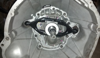
This image shows a slight variation on the above measurement method.
With the bearing, as provided
by the clutch kit installed, a scale is inserted into the bellhousing window. Because it's a low-hat clutch
and the bearing supplied is GM's shortest version, the gap shown is significant at ~3/4".
We
consulted the chart below, chose a longer bearing and were back on track with our project.
Measurement Option III: External Style Fork Travel
This option still requires a mock-up of
the bellhousing assembly, but is superior to Option II above when there is no adequate window to sight your
measurement through, and if you have a short bearing retainer to test with.
Measure your clutch arm and record its leverage ratio, i.e., pivot to release bearing centerline and pivot to pushrod dimple centerline. If your release arm inner section measures 2.3" and your release arm outer section measures 3.6", the you would divide the outer number by the inner number to obtain the arm’s ratio, e.g., 3.6" / 2.3" = 1.56:1 ratio.
With the clutch disc and pressure plate installed and ready, insert the release fork in its proper orientation into the bellhousing with its tail through the bellhousing window and its retention spring (if applicable) onto the bellhousing pivot. Temporarily clip the short release bearing (or the Novak adjustable release bearing fully collapsed) onto the fork and then insert the transmission bearing retainer snout securely into the bellhousing bore. Install the bellhousing to the engine block.
Find a datum point to which you can fix a scale. Move the release fork back and forth to obtain a linear travel measurement of the outer edge of the fork. Now, do your math. Divide that number by the leverage ratio of your release fork. Now subtract your air gap allowance. The result is how much longer of a bearing you want over the one you just tested with.
|
1. Fork travel: 0.6". |
Option IV: Internal Style Fork Travel
 |
This method is best for fully enclosed bellhousings that use an internal cross-arm (with the pivot on the opposite side of the push-point) instead of the traditional external release arm, such as with the Jeep AX15 to 4.0L style bellhousing.
you do not typically need to measure the ratio of a cross-style release arm as they are usually symmetric or that the push and pivot points at least evenly spaced from centerline.
 |
Temporarily clip the short release bearing (or the Novak adjustable release bearing fully collapsed) onto the release arm. With the clutch disc and pressure plate installed and ready, and the transmission bolted to its bellhousing, insert the release fork in its proper orientation (if not fully symmetrical) into the bellhousing, over the transmission bearing retainer snout and then snap on the retention spring (if applicable) onto the bellhousing pivot (see adjacent image). Install the bellhousing to the engine block.
Reach your finger into the slave cylinder port and pull the clutch arm fully back. Insert your scale into the port against the push-point of the arm without yet moving the arm. Read the scale and record your measurement against the datum point of the machined face of the port. Now, push the scale frontwards until the bearing stops against the pressure plate fingers. Record your measurement.
Take your two measurements above to determine your free-travel. Divide that measurement by a divisor of 2. Now subtract your air-gap allowance. The result is how much longer of a bearing you want over the one you just tested with.
| Let’s use the following numbers as examples: 1. Fork travel: 1.2". 2. Leverage ratio: 2 3. Air gap allowance: 0.125" 4. Disc wear / finger rise allowance: .125" 5. Test bearing overall length: 2.35" Result: (1.2" / 2) - 0.125" - 0.125" + 2.35" = 2.7" overall length bearing required. |
 |
|||||||||||||||||||||||||||||||||
The pricing shown is a recent check of prices on the street, so that the installer can choose a bearing of similar length and reduced cost. Some of these bearings are no longer available or are excessively priced.
An alternative to the above bearings is the Novak fully adjustable release bearing assembly. Read more about it here. |

This chart shows the length of the bearing in inches. Most auto parts stores only stock a couple of these release bearings and they may not be the best ones for your swap. This chart lists bearings by the critical "A" measurement; groove to face dimension as referred to in this article.
Install the transmission on the clutch housing. The release bearing must be able to move away from the diaphragm spring approximately 1/16 to 1/8" (this is the "free play"). At this point you should be able to move the release bearing back and forward with the fork. The bearing, when against the clutch, should leave the release fork positioned at 4 or 5 degrees LESS than a right angle with the engine centerline and allow it to be moved away from the clutch 1/16 to 1/8". If this condition does not exists, do not install the assembly into the Jeep until it does. If not, you may need a different clutch release bearing or pivot or you may have the wrong fork.
As stated earlier in this article, if you are switching from a three-finger type to a diaphram style pressure plate, you will require a shorter throwout bearing. The inverse is, of course, true if you are going the other way.
The bearing must clear the clutch or it will turn all the time and will wear out quickly—also the clutch may slip as it may be partially released.
Clutches not releasing is nearly always caused by too short of a release bearing and correspondingly, the release arm not having full mechanical advantage by starting its travel at a foremost angle that is not complimentary to its rearmost angle when completely depressed.
 |
 |
| This is the incorrect method for installing a GM release fork onto its throwout bearing and will cause malfunction and / or component breakage. | This is the correct method for installation a GM release fork onto its throwout bearing. |
 |
| 1. Coat this groove and fork tangs with a thin layer of grease 2. Pack this recess with grease |
Final Considerations▼
At this point (finally) the engine and transmission are ready for installation and hookup of linkage. Install the remaining bellhousing and transmission bolts if these parts do not have to be removed again.
The engine, transmission, and transfer case should now be installed in the Jeep. With the engine mounted, the connection of the clutch linkage can proceed.
Regardless of whether the stock linkage pushed or pulled, it must do so in as straight a line as possible. This will keep friction to a minimum.On installations where the engine must be moved (such as pre-1971 CJ's) the clutch bracket that supports the frame end of the bellcrank must be relocated. This must be to a location that will put the bellcrank at a right angle to the engine and level from side to side (parallel to the ground).
On 1972-86 CJ's where a bracket must be made to support the Jeep clutch cross-shaft, the cross-shaft must end up at a right angle to the engine in both the vertical and horizontal planes.
The arms on either style bellcrank must be positioned for maximum mechanical advantage. This means they cannot angle more than about 35 to 40 degrees from either side of a right angle to the push (or pull) rod that they connect to. This alignment angle is established at the bellcrank and the operating rods are then modified to whatever length is required to keep the bellcrank or cross-shaft at this position with the release bearing at least 1/16" off the three release arms of the pressure plate.
Have a helper push the clutch pedal to the floorboard and hold it there. Check the air gap between the flywheel and the clutch disc with a feeler gage. As stated previously, it should be .030" for a diaphragm clutch and .040 to .050 for a coil spring clutch.
Release and adjust the linkage until the air gap is correct for the type of clutch being used.
Bellhousing Alignment▼
 On any engine using a standard shift transmission, with or without an adapter, it is
important to check the bellhousing locating bore location relative to the crankshaft. The potential for
transmission failure or premature wear is so great, due to misalignment at this point, that no engine should be
assembled without being checked. The checking procedure is quite simple. Correcting misalignment is not so
simple but must be done to insure normal service from the transmission. A dial indicator is required, as well as
a suitable means to mount this instrument on the engine crankshaft.
On any engine using a standard shift transmission, with or without an adapter, it is
important to check the bellhousing locating bore location relative to the crankshaft. The potential for
transmission failure or premature wear is so great, due to misalignment at this point, that no engine should be
assembled without being checked. The checking procedure is quite simple. Correcting misalignment is not so
simple but must be done to insure normal service from the transmission. A dial indicator is required, as well as
a suitable means to mount this instrument on the engine crankshaft.
A dial indicator is a device that has an arm or contact point, suitably connected to a pointer, that moves in front of a dial with markings on its face. These markings usually represent .001" each. The purpose of a dial indicator is to measure in thousandths of an inch that can be read directly on the dial of the indicator.
To check a bellhousing, mount it on the engine it's going to be used with, make sure there are no burrs or dirt on the block or bellhousing. All bellhousing to block bolts should be in and tight. Mount the dial indicator on the crankshaft of the engine using a suitable magnetic base attachment or mechanical clamping means. The contact point of the indicator should be touching the bore of the bellhousing. The indicator must be mounted rigidly enough so it does not move on its mounting to prevent false readings. Rotate the engine by hand with the spark plugs removed and observe the reading on the dial. Keep adjusting the dial assembly until the needle moves the least amount per rotation. When you have acheived the least amount of needle movement throught he 360 degree sweep of the indicator, this is your runout. you can then determine the direction it is offset by the movement of the needle.

- Install dial indicator base to the flywheel using a magnetic base, or use the crank bolts.
- Remove the spark plugs from the engine. Have an assistant rotate the engine crank with a wrench.
- Read the runout and mark the "high" and "low".
- If runout exceeds .005" to .007", then you must install offset dowel pins, of the appropriate value and install them in the direction to correct the offset.
- Check your work again with the indicator.

Offset dowel pins. Image courtesy of Lakewood.
The total number of thousandths misalignment of the bore relative to the crankshaft is read directly on the dial. Total runout should not exceed .007", with .010" being maximum. The greater the misalignment, the sooner transmission problems and failure will occur. A symptom of misalignment is unusual wear of the pilot bushing. We have checked stock Chevy bellhousings on engines that were out more than 1/32" (.032"). Some Ford ones are reportedly worse. Anything over .010" runout must be corrected before the engine and bellhousing are put in service or you can count on pilot bushing, transmission, and clutch problems, followed by transmission failure. The simplest way to correct misalignment is to try another bellhousing or bellhousings. Machining the bellhousing is the best cure but offset dowel pins are simpler. Shims between the block and bellhousing will also work if you have the patience to use this method. Offset dowel pins are sometimes available from speed shops, parts houses and other specialty suppliers.
For Reference▼
The pressure plate must move about .100 to .120 of an inch to RELEASE THE DISC and provide .030 to .050 air gap between the disc and the flywheel.
- A 9" clutch has about a 4.5-to-1 arm or diaphragm ratio.
- A 10.5" clutch has about a 6-to-1 arm or diaphragm ratio.
- An 11" clutch has about a 6.6-to-1 arm or diaphragm ratio.
The release bearing must move away from the fingers or diaphragm sping at least 1/16"
(.0625 rounded off to
.06) for freeplay.
The release fork ratio is determined as described in the release fork section.
Example: A 10.5" clutch and a #RAGM GM release arm (2.17 ratio).
So, 0.120" required movement multiplied by the ratio of a 10.5" clutch equals .72" plus .06" movement of release bearing for freeplay equals .78 of an inch. Multiply .78" by the ratio of the release fork (2.17") equals 1.69" (or 1-11/16") of travel required where the linkage attaches. It doesn't matter if the linkage is mechanical, cable, or hydraulic, it must be able to move the end of this arm with this pressure plate the above indicated amount in order to properly release the clutch disc.
For comparison, using the same release arm with a 9" clutch only requires about 1-5/16" movement while the 11" clutch requires almost 1-7/8" of movement -- nearly 9/16" more. It is the ratio of the pressure plate that makes this difference. This is also exactly why the hydraulic slave system on 1980 to 1986 4 cylinder CJ's will usually not completely release a 11" clutch on a conversion engine. It does not have the necessary travel. In this particular Jeep both the operating and slave cylinders would have to be changed to get more travel.
However, if the slave system is engineered correctly with the proper ratios, full release can be attained with 10.5" and even 11" clutches. See the Novak #HCR3 kit.
Symptom:
Clutch drags. It won't release completely and the transmission grinds when
shifted
| Possible diagnosis | Likely solution |
| Linkage out of adjustment or binding | Adjust or repair linkage |
| Master cylinder leaking internally | Measure master cylinder linear travel vs. slave cylinder linear travel. Replace master if excessive descrapancy |
| Release arm too long for the linkage system | Determine the correct ratio (as per instructions above) and shorten the arm |
| Release arm sitckout angle incorrect | Change the length of the release nearing, pivot or both, if necessary |
| Release arm hits bellhousing opening preventing full travel of the arm | Grind clearance as necessary on the bellhousing |
| Engine is shifting on the motor mounts, wasting linkage travel | Repair, rebuild or replace the motor mounts as necessary |
| Pilot bushing binding on the input shaft. Possibly damaged at installation or resulting from a misaligned bellhousing | Replace the pilot bushing. Refer to the bellhousing alignment procedure in the Novak guide |
| Input shaft pilot is "bottoming out" in the crankshaft bore | Shorten the input shaft by grinding or deepen the bore of the crank by drilling |
| Clutch disc hub is damaged or assembled incorrectly | Replace the disc |
| Pressure plate or cover is warped | Replace the pressure plate assembly |
| Excessive run-out at the face of the flywheel | Check the crank flange for burrs and remove them, or reface the flywheel |
| Incorrect flywheel to crank hub bolts. The bolt heads are driving the disc | Use the correct, special flywheel bolts |
| Clutch disc is installed backwards. The bolt heads are driving the disc | Disassemble and turn the disc around |
| Clutch disc is too large. The edge of the disc is interfering with the pressure plate assembly | Specify a smaller disc |
| Clutch arm to throwout bearing retaining clip is tweaked on the bearing lip (progressive worsening) | Replace throwout bearing if damaged and reinstall the arm and clips correctly |
Symptom:
Clutch Slippage
|
Possible Diagnosis
|
Likely Solution
|
|
Linkage out of adjustment or binding
|
Adjust the linkage to create proper amount of slack in the system
|
|
Release bearing is too long, holding the clutch in a slightly disengaged position
|
Use a shorter release bearing. See the chart in the text
|
|
The friction surface on the flywheel, pressure plate or disk is glazed (usually from
heat)
|
Resurfacing and replacement of clutch assembly
|
|
The clutch is too small and/or the spring load is too light
|
Use a larger clutch or a heavier spring. The former is often preferable. Extreme cases
may require both
|
|
Oil on the clutch disc
|
Repair the oil leak (typically the engine rear main or oil pan if not the transmission
from seal) and replace the disc
|
|
Broken or fatigued springs
|
Replace the pressure plate
|
Symptom:
Clutch chatters when engaging
| Possible diagnosis | Likely solution |
| Damper springs in the clutch disc hub or the marcel spring between the facings is fatigued | Replace the clutch disc |
| Friction surface on the flywheel or pressure plage is glazed from the heat | Resurface or replace as necessary |
| Clutch disc is running out on the input gear (hub problem) | Replace the clutch disc |
| The flywheel or pressure plate surface is running out | Reface or replace as required |
| Oil on friction surfaces | Repair the oil leak (typically the engine rear main or oil pan if not the transmission from seal) and replace the disc. Avoid parts contamination upon reassembly |
| Linkage works erratically | Inspect the linkage, paying special attention to the holes in each lobe. Repair or change the linkage as required |
| Play in the motor mounts allowing for shifting of the powertrain, relative to the linkage | Change or repair the motor mounts |
Symptom:
Pedal pulsates when pushed to floor (3-finger coil spring type only)
| Possible diagnosis | Likely solution |
| Clutch is over-releasing and the release fingers are hitting the disc hub damper springs | Reduce linkage travel (see above text) |
Symptom:
Pedal pulsates at start of release
| Possible diagnosis | Likely solution |
| Flywheel run-out | Check for burrs on clutch and flywheel mounting flanges |
| If a three-finger type, fingers may not all be the same height | Have the pressure plate readjusted by a rebuilder or replace the pressure plate |
| Excessive clearance between release bearing and retainer | Replace the retainer or on mismatched parts, sleeve retainer up to the release bearing size, plus slip fit |
Symptom:
Noise; clicking or rattling at idle RPM with the pedal released
| Possible diagnosis |
Likely solution |
| Broken spring(s) | Replace the pressure plate
|
Symptom:
Noise; whirring or grinding when clutch is released (pedal depressed)
| Possible diagnosis | Likely solution |
| Failing clutch release bearing | Replace |
Symptom:
Noise; chattering or "buzzing" when clutch is released
| Possible diagnosis | Likely solution |
| Excessive pilot bushing to input gear clearance. Often resultant of bellhousing misalignment | Replace pilot bushing. Clearance should be .001 to .004 |
Symptom:
Pedal is hard to push and hold down
| Possible diagnosis | Likely solution |
| Improperly set-up linkage system | Change as required (see text) |
| Pressure plate spring load excessive for linkage | Reduce spring load, or, if high pressure clutch is required then modify the linkage to give the minimum travel that will still release (i.e., provide the required .025 air gap) and leave a finger clearance of 1/16" |
Symptom:
Air in Hydraulic Release System & Won't Fully Release
| Possible diagnosis | Likely solution |
| Air ingress and/or internal fluid leak in master cylinder | Change as required |
| If leaking fluid is present at line or slave cylinder, leaking line joint or slave hydraulic cup | Change or repair as required |

A cutaway view of a clutch assembly, three finger
type.
Image courtesy of McLeod Industries.