


The Novak Guide to
Rebuilding the Jeep / IH Dana 18 Transfer Case
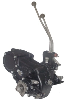
The Dana Model 18
The Dana Model 18 transfer case makes for an enjoyable and satisfying rebuild project. Individuals can obtain outstanding results with some information, good parts, and pride in their work. A non-leaking, quiet and cooler running Dana 18 can be acheived with modern bearings, better seals and gaskets, improved lubricating fluids and a specially hardened intermediate shaft.
Preparation for the Rebuild
Rebuilding Tools & Supplies
You probably already have most of the tools required to build a transmission, including wrenches, ratchets, screwdrivers, scrapers, hammers, etc. Additional tools and supplies that may be less common:
- A urethane or plastic mallet
- Bearing puller (helpful, but not required for a T90 rebuild)
- Pliers, snap ring, bevel (Eaton) style
- Large arbor press or hydraulic press
- Transmission assembly grease. Never use axle or conventional grease as it will not dissolve into the fluid and plug passages to the ruin of your transmission. Choose something tacky, which will allow you to stick parts together. We use Smart Blend Synthetic Assembly Lubricant #5500. Petroleum Jelly is a decent alternative. Store your assembly lube in the fridge to increase the tackiness for loading those pesky needle bearings. Your assembly grease will melt into the gear oil upon first operation of your fresh transmission.
- Gasket sealants: RTV (Permatex Black or Grey, The Right Stuff, Aviation Gasket Sealer, etc.)
- Safety glasses or goggles. Take a poppet ball, snap ring, solvent or case-hardened shaft / gear fragment in your eye and you’ll become a convert
Cleaning
You may choose to pressure wash the transmission prior to putting it on your bench. If you plan on doing a partial rebuild (upper end / mainshaft changeout) only, getting it as clean as possible prior to disassembly is important. If you do this, do not allow the transmission internals to be in contact with water for any real length of time.
If you are going to be solvent bathing your transmission and its disassembled components or hot tanking the case, you may forego the pressure wash. Scrape as much grease off the case as you can and then clean up the bench. Don’t worry too much about getting the outside of the case completely clean because it will be completely disassembled and cleaned. Your spouse’s dishwasher is actually a decent option, but we’ll advise that the interpersonal consequences could be quite heavy.
Separating the Model 18 Transfer Case & Transmission (without Warn Overdrive option)
Remove the five bolts on the sheet metal power take-off cover on the rear of the transfer case and remove the cover. Remove the cotter pin in the nut at the center of the input gear and remove the nut. Cottered nut uses 1-5/16" socket, Nylock® nut is 1-1/4". Remove the gear from the output shaft taking care not to drop the hub washer or nut into the transfer case. The transfer case can now be separated by removal of the five retaining bolts. One bolt is on the front side near the front driveshaft yoke.
Separating the Model 18 Transfer Case & Transmission (with Warn Overdrive option)
 If the Model 18 is equipped with Warn overdrive, it must be removed before the transfer case can be removed from the transmission. To accomplish this, disengage the Warn overdrive. Remove the shift linkage from the O/D. Remove the five bolts that hold the O/D to the transfer case. The four bolts on the back cover of the O/D do not require removal. The O/D housing can now be pulled straight back for removal. If necessary, the housing can be tapped back (while pulling on by hand) with a plastic faced hammer or block of wood. Be careful, the housing is aluminum and is easily damaged. Do not attempt to pry the overdrive off. Note that bearing seat constriction may prevent easy removal. In this case, remove the rear cap of the overdrive. Attach a slide hammer to the six-spline tube and tap it rearward. With the unit now separated, continue as indicated.
With the housing removed, the hub assembly is now accessible. Use a light to look in the hole in the center of the hub assembly. You should see a square shaped flat wire lock ring in a groove. A thin pair of long nose pliers can be used to squeeze the ends of the lockring together for removal. The lockplate (or washer, in common parlance) that was retained by the lockring can now be removed. With these removed, use a regular 1/2" drive socket extension to remove the special hub retaining nut. This has a regular right hand (counter-clockwise to loosen) thread. When the hub nut threads disengage, the hub can be removed from the output shaft.
The transfer case can now be separated by removal of the five retaining bolts. One is on the front side near the front driveshaft yoke.
Model 18 Transfer Case Disassembly
On two-lever transfers, the lock screw, shifter pivot pin, shift levers and anti-rattle springs will have already been removed when the transfer case was removed from the vehicle. On single-lever shifters, remove the shifter links taking note of their relationship for reassembly.
Remove both front and rear drive shaft yoke nuts and washers. A large pipe wrench or bench vise will hold the yokes from turning while the nuts are removed.
Pull off the yokes using a two-leg gear puller of suitable size.
Remove the bottom cover (oil pan).
Remove the bolt and retainer plate from the intermediate shaft.
Remove the four bolts holding the rear bearing cap to the case and remove the cap as an assembly with the speedometer gear. The parking brake backing plate is also retained by these bolts on Jeeps so equipped. Take care with the adjusting shims that are between the cap and case.
Use a soft drift to drive the intermediate shaft out (towards the rear of the case). Shaft is larger on rear, driving out forward will damage the case. Remove intermediate gear, thrust washers, bearings from case.
Remove the plugs, springs, and poppet balls from both sides of the front output bearing cap. Engage front wheel drive (left shaft forward).
Remove the five bolts holding the front output bearing cap to the case. Tap the cap with a soft hammer to break it loose and remove it as an assembly with the shaft, shifter clutch, shifter fork and shift rod. Be careful not to lose the little bullet-shaped interlock that "floats" in the passage between the shift rods. The front bearing cap assembly does not usually require disassembly unless the Jeep has been used very hard in 4WD (such as plowing snow) or has not been equipped with free-wheeling hubs. If the shifter shaft seals are to be replaced, the cap must be disassembled to remove the seals. To do this, loosen the set screw on the shift fork and remove the fork, shifter clutch, and shift rod. Remove the snap ring from the housing and remove the bearing and front output shaft.
Using a soft hammer or the end of a block of wood, drive the output shaft towards the rear of the case to remove the rear bearing cup from the case. Drive a large screwdriver or similar shaped tool between the front bearing and the output gear to separate the gear enough to remove the snap ring from its groove in the shaft. Never use the gear to pry against when removing this bearing. It will chip a tooth if this is done. When this snap ring is removed from its groove and rests on the forward part of the output shaft, the shaft can be pulled out of the gears towards the rear of the case. The gears, (low slider and output) thrust washers, and snap ring can now be removed from the case.
If necessary, the rear bearing cone can be removed from the shaft with a drift and hammer or by inertia caused by striking the end of the shaft on the end of a block of wood. When the snap ring is removed from the groove in the output shaft it should never be re-used. Always replace with a new snap ring, as included with our intermediate and master rebuild kit.
Remove the setscrew and remove the shift rail and fork from the case taking note of its position so it may be reinstalled in the same relationship as it was removed. We use the shank of a screwdriver, inserted through the end hole of both shift rails and twist / pull the rails out in alternating manner.
|
1. Companion Flange and Oil Seal |
25. End Yoke |
49. Cone and Rollers |
Model 18 Inspection
Wash all parts thoroughly in a suitable solvent to facilitate inspection. Check the case for cracks that may run from the intermediate shaft bore down to the bottom cover surface or from the output shaft bearing bores down to the bottom cover surface. If cracks are present here they will usually be of the "hairline" type. A very clean transfer case and a magnifying glass are advisable for inspection. Unfortunately, if the case should be cracked, it must be replaced as there is really no satisfactory way to repair it.
Check the intermediate shaft for signs of wear. The 3/4" and 1-1/8" shafts will almost always need replacing. The 1-1/4" shafts hold up longer but any sign of rollers working on the shafts should be cause to replace, not only the shaft, but the rollers and thrust washers as well. Our transfer case rebuild kits include these parts. The intermediate shafts we make are the only source we know of high quality transfer case shafts. Shafts from other sources are imported and are extremely poor quality, low grade steel, shallow depth of hardness, etc.
Inspect the bore of the intermediate gear for roughness, pits, and wear. Use your thumbnail to judge the presence of an objectionable bearing wear ridge in the bore.
Check the condition of the output shaft and the inside of the output shaft drive gear for signs of galling caused by running in low range with the transfer case low on oil. Replace if necessary.
Check the output shaft roller bearings and cups for pitted and spalled surfaces. Replace as necessary.
Check the size of the bronze bushing in the bore of the rear output shaft. This pilots the front output shaft and may be in poor condition due to a bent or badly worn (slip splines) front driveshaft. This bushing bore is .628" when new. If over .630" it should be replaced. If replaced, it may require reaming or honing to the .628" size as this type of bushing can compress undersize when installed. We can install this new bushing for you for a nominal fee. Note that all Novak master rebuild kits for the Dana 18 include this new bushing.
Hypoid gear oil is sulphurized higher than transmission oil and can be mildly corrosive to the non-ferrous alloys used for bushings and thrust washers in these transfer cases.
A 75W-90, API-GL5 or MT-1 rated fluid is very good.
Inspect the gear teeth for chips and pits, particularly on the drive face teeth. Small pits from rust due to moisture condensation should not present a problem.
Polish any rust off the exposed ends of the shifter rails so the shafts won't ruin the new seals when installed. Check to see if the shifter forks are bent by sliding them on the shaft—the ends should be at right angle to the shaft.
Install new output shaft oil seals in the front and rear output caps. Install new shifter shaft seals if the old ones are leaking. These are difficult to remove without the proper puller. Trying to pry them out will usually damage the bore allowing oil to leak out around the outside of the new seal and the bore. Care taken here will help eliminate oil leaks.
Use a smooth file to deburr all the gasket surfaces on the case, front output cap and rear output cap.
Carefully clean the adjusting shims for the output shaft bearings using ScotchBrite or similar abrasive. New shim kits are available (typically supplied with our gasket kit) and are automatically include in our master rebuild kits.
Model 18 Reassembly
The assembly process will be a reverse of the disassembly. Watch for the following as assembly progresses:
The front output cap gasket thickness is a factor in the end-play adjustment of the rear output shaft. This is because the front bearing cup seats against the bore in the front cap. The front cap must be reassembled and installed on the case along with both shift shafts and forks. If the shift fork retaining screws were drilled for safety wire, be sure to re-wire. The front output bearing cup is installed in the case and seated firmly against the front output cap.
 Be sure not to leave out the bullet shaped interlock pin that "floats" between the shift rods in the front output cap, unless you wish to convert to true twin-stick operation, which runs the risk of an operator cross-shifting the transfer case if not cognisant of the situation.
Install the low range sliding gear and output gear in the case with the shift groove on the gear facing to the rear and engaged on the shift fork. Install the output shaft part way through these gears, then install the output thrust washer (tangs in slots on shaft) and a new snap ring followed by the front bearing cone. It takes patience and caution to make this assembly sequence. The snap ring must be worked back on the shaft along with the front bearing cone until the snap ring will enter its groove on the shaft. The front bearing can now be seated against the thrust washer.
The rear output bearing cone can now be installed on the shaft followed by its bearing cup which can be tapped into the case until it seats lightly against the rollers of the cone. This will position the bearings for adjustment procedure that follows.
Output Shaft Endplay
 Hold the rear output cap on the rear bearing and measure the gap between the cap and the case with a feeler gauge. Add .010 to the gap thickness to obtain the thickness of the shim pack for the initial setting. (Note that the shims are available in thickness' of .003, .010, and .031.)
Install the initial shim pack and rear cap and tighten the four rear bolts to 30 foot pounds. The output shaft, gear, and bearings assembly must now be moved rearward to seat the rear bearing in the rear cap. The easiest way to do this is to use the end of a block of wood and a hammer and rap the rear cap (not the shaft). The inertia of the impact will seat the rear bearing. Failure to fully seat these bearings is a common occurrence, and stacking an unholy number of shims up to get endplay is not the answer. It may sometimes be necessary to install the yoke, speedo drive spacer, etc. and torque the yoke nut to fully seat this assembly.
When installing the Novak intermediate shaft, install the leading o-ring after the shaft has entered the rear bore and then apply a coat of grease to ease its installation into its own bore at the front of the transfer case. Install the second o-ring and grease it as well. This is to minimize the risk of damaging the o-ring seal during this installation process.
Install the initial shim pack and rear cap and tighten the four rear bolts to 30 foot pounds. The output shaft, gear, and bearings assembly must now be moved rearward to seat the rear bearing in the rear cap. The easiest way to do this is to use the end of a block of wood and a hammer and rap the rear cap (not the shaft). The inertia of the impact will seat the rear bearing. Failure to fully seat these bearings is a common occurence, and stacking an unholy number of shims up to get endplay is not the answer.
Attach a dial indicator to the case with the contact tip of the instrument on the end of the rear output shaft. Push and pull gently on the shaft by hand while reading the end play on the indicator. (Factory spec for end play is .004 to .008 but a better job results if .002 to .006 is maintained. This is an important adjustment and cannot be done by eye or feel. Add or subtract shims as necessary to obtain the desired end play. Be sure to seat the bearing as outlined previously each time the shim pack is made thicker.
After the proper thickness shim pack has been established, remove the rear cap and shims and apply a thin coat of shellac or sealant spray. Reassemble before the spray dries and torque the bolts (30 ft. lbs.), and recheck end play, which should be the same as before (.002 to .006).
Install the intermediate gear, bearings, and thrust washers in the case. Cage type bearings of 3/4" and 1-1/8" diameter are simple to install and should be either lightly greased or lubricated with gear oil at assembly.

Let's all just be honest with ourselves and admit that this is the coolest Dana 18 PTO cover available. It's thicker plate aluminum construction resists warpage like the thin, factory steel versions. It is media tumbled, anodized and machine engraved.
Uncaged rollers (quantity 48) and spacers (quantity 3) used with the 1-1/4" shaft are best retained in the gear bore with frozen petroleum jelly or Smart Blend Synthetic Assembly Lubricant #5500. The thrust washers can be "glued" to the faces of the gear with this methodalso. The gear, rollers, spacers, and thrust washers can be easily positioned in the case to accept the intermediate shaft which is installed from the rear of the case, tapped into position, and safetied with the lock plate and bolt. (Note that this gear and shaft may be removed from the transfer case for service while the case is in the vehicle. This is easily accomplished by removing the bottom cover [oil pan] from the transfer case.) Never mix old and new bearing rollers. There is enough difference in size to cause the new rollers to carry a greater portion of the load. This will cause premature failure of all the rollers.
Cap of the Dana 18 with it's rear PTO cover and it's bottom cover and their respective gaskets and your preferred RTV (we like the Right Stuff - RTV posing as a can of CheezWhiz™ at your auto parts house...). Lay down only a thin layer of silicone on each side of the gasket. Solvent clean the steel metal mating surfaces to remove any oil. Tighten the bolts by hand just enough to barely start to squeeze the RTV. Wait several hours and then tighten slightly more, using a tiny wrench and minimal force. Overtightening of the bolts is too common, and results in cover warpage and leakage.
Install new output yoke oil seals and install yokes. Torque to 175 ft. lbs.
Check unit for freedom in all modes and ranges by hand turning.
Enjoy your improved Jeep.